![]()
![]()
![]()
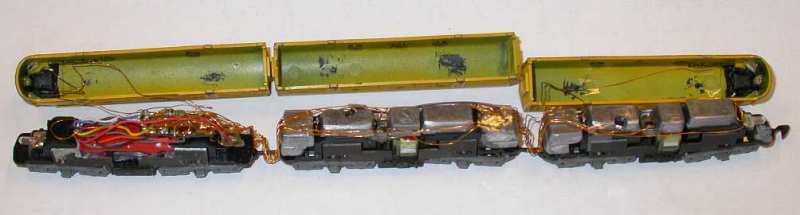
One decoder for two motors
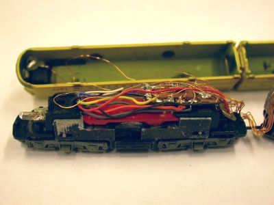
Here is a F7 ABA unit of the UP (Märklin). In the left A unit the Digitrax DN142 decoder is located. This A unit has become a dummy now and the B unit got the motor. The left A unit is normally the front. All motorized engines are ballasted with lead for improved pulling power. The electrical connection is done by insulated copper wires. Despite the numerous wires the engine can negotiate the middlest Märklin radius, but it does not work with the industial radius. For later DCC rebuild the use of fine cables is forseen. The Digitrax decoder has 4 funtional outputs controlling the ligth and the strobe ligth on both ends. The normal ligth is located in the lower engine headlight the strobe is operating in the top headlight. Normal ligth uses the standard ligth bulb, strobe is done by a very brigth white LED. The LED is lied flat for better fit and glued to the engine shell. A connection between the LED and the top headlight has been made by clear glue. LED and light connector are pinted black to avoid any lstrobe lighting outside the headlight. Just a close view to the A unit with decoder. The cables of the decoder are soldered on a part of an old circuit board
to get the electric connection to the copper wires.The engine's body has been milled to accept the decoder.
|
![]()
Powered by  http://www.3RWorks.com